Bearing Ratio Curve is the integral of an Amplitude Distribution Function (ADF) used to quantify the ratio of material to air in a scanned surface. This property is known by many names including:
Abbot-Firestone curve
Abbot-curve
Bearing area curve
Material ratio curve
All refer to the same value.
Visualize a bearing ratio curve as taking a horizontal slice through the scan at a given depth to find the ratio of material to air. For example, in the image below, the blue line indicates a depth plane of 0 µm. A plane drawn at that height would be 100 percent air, as there is no material at that height.
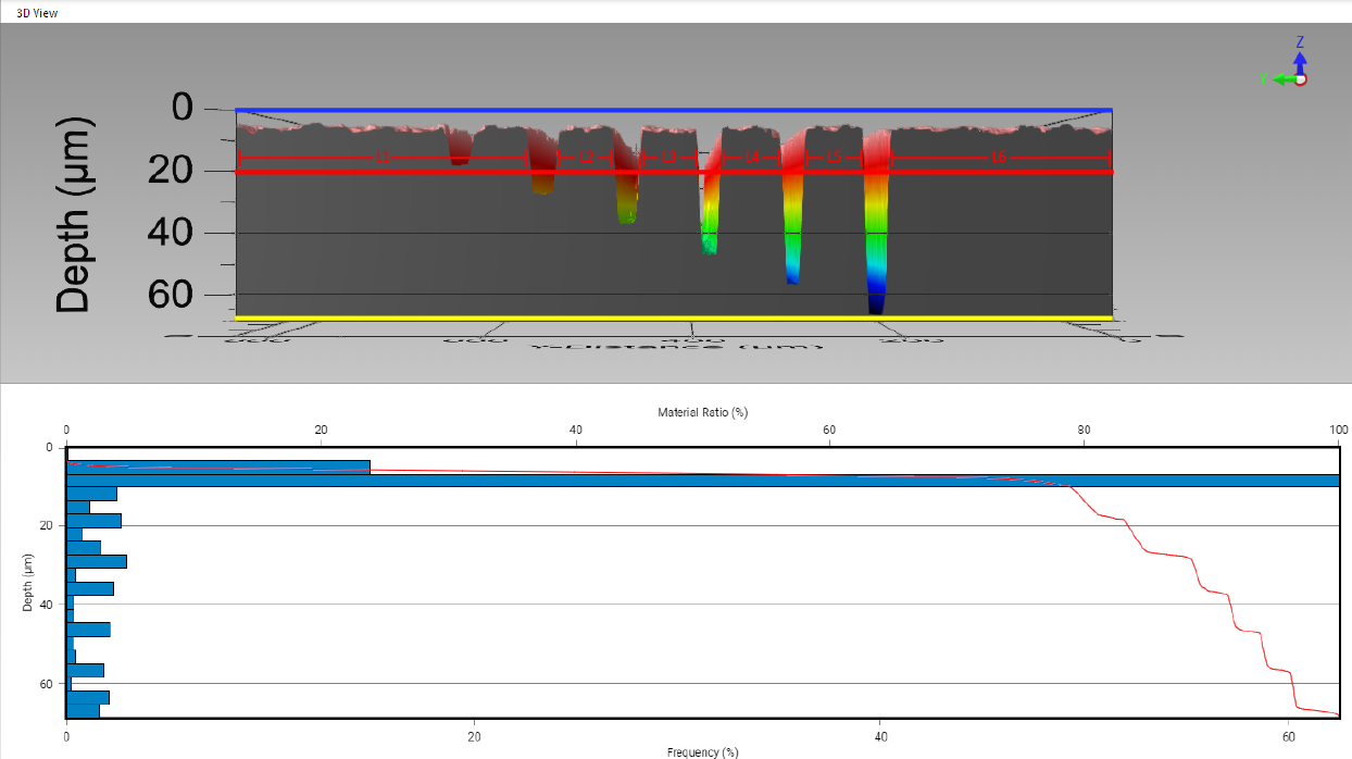 |
Example Bearing Ratio Curve: Dicing Saw Qualification |
However, a plane drawn at a 20 µm depth, illustrated by the red line, has a mix of material and air present. To calculate that ratio, take the sum of the lengths of material (L1, L2, L3...) and divide by the total length of the scan. At this depth, the ratio is roughly 84% surface to air. The further into the sample, the more the ratio tips towards 100%. In this case, this occurs just past the bottom of the lowest dice channel at roughly 66 µm (yellow line).
Bearing ratio curve includes a histogram function displaying the frequency of material relative to depth.