 |
The FFT (Fast Fourier Transform) Filter operator separates short wavelength components from long wavelength components in an image. It also separates components of a surface that lie in a specific direction. FFT Filter must be used on an image with no invalid pixels. Use Fill In Invalids or Remove Outliers operators to fill invalid pixels. |
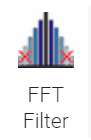
The FFT Filter dialog box contains the Starting Image, Excluded Image, and Included Image output previews.
Output Excluded image shows only values that are less than the selected cutoff length. Output Included image shows values greater than the cutoff length, and is the default selection.
Power Spectral Density (PSD) Image is a 2D representation of the filtered spatial frequencies. Higher spatial frequencies are shown in the center, while lower frequencies are shown at the edges. The blue to white gradient shows how often a frequency occurs.
The PSD Threshold (%) slider filters noise in the PSD image based on the cutoff percentage selected. Values below the cutoff are set to the minimum value and displayed as blue pixels. Changing this value has no effect on the resulting image.
FFT Filter requires the image dimensions be a power of two (e.g. 256 x 512), otherwise the operator pads data from the edge to the next nearest factor of two. Mirror X and Mirror Y pad edge pixels by mirroring values around the selected axis. If neither are selected, a zero value is used to for all pixels padded to the edge, which can cause artifacts in the resulting image.
Low Pass filtering separates low and high frequency information in an image by varying the Cutoff wavelength in the X and Y direction. Spatial frequencies outside of the red ellipse are excluded from the filter. Cutoff values determine the size of the ellipse. Lock Aspect Ratio maintains the ratio between the X and Y cutoff values when either are changed.
Low Pass requires a filter type be selected. The Ideal filter uses the cutoff values as a hard stop, while Gaussian applies a slight blur around the cutoff length which tends to look more natural to the eye. See the Low Pass filter example below:
 |
 |
 |
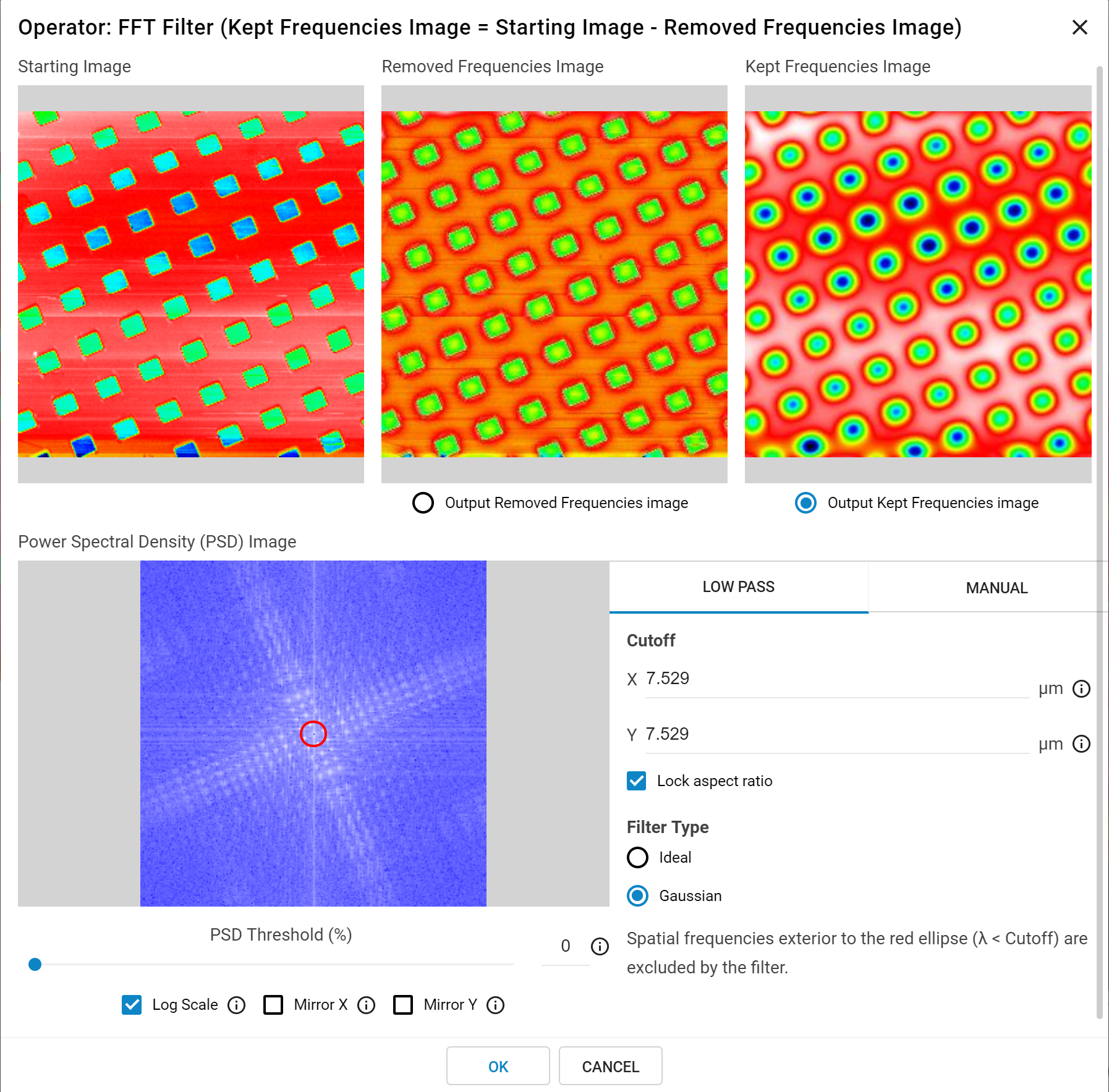
Original Image |
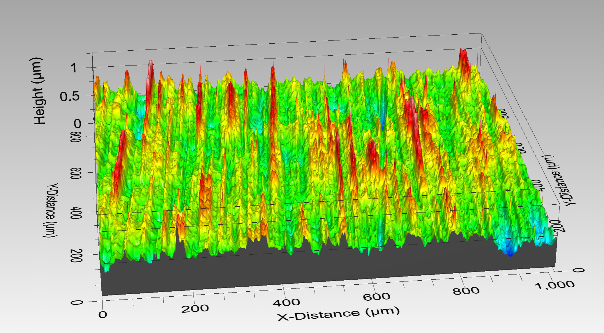
40 µm Low Pass Filter - Kept Frequencies Image |
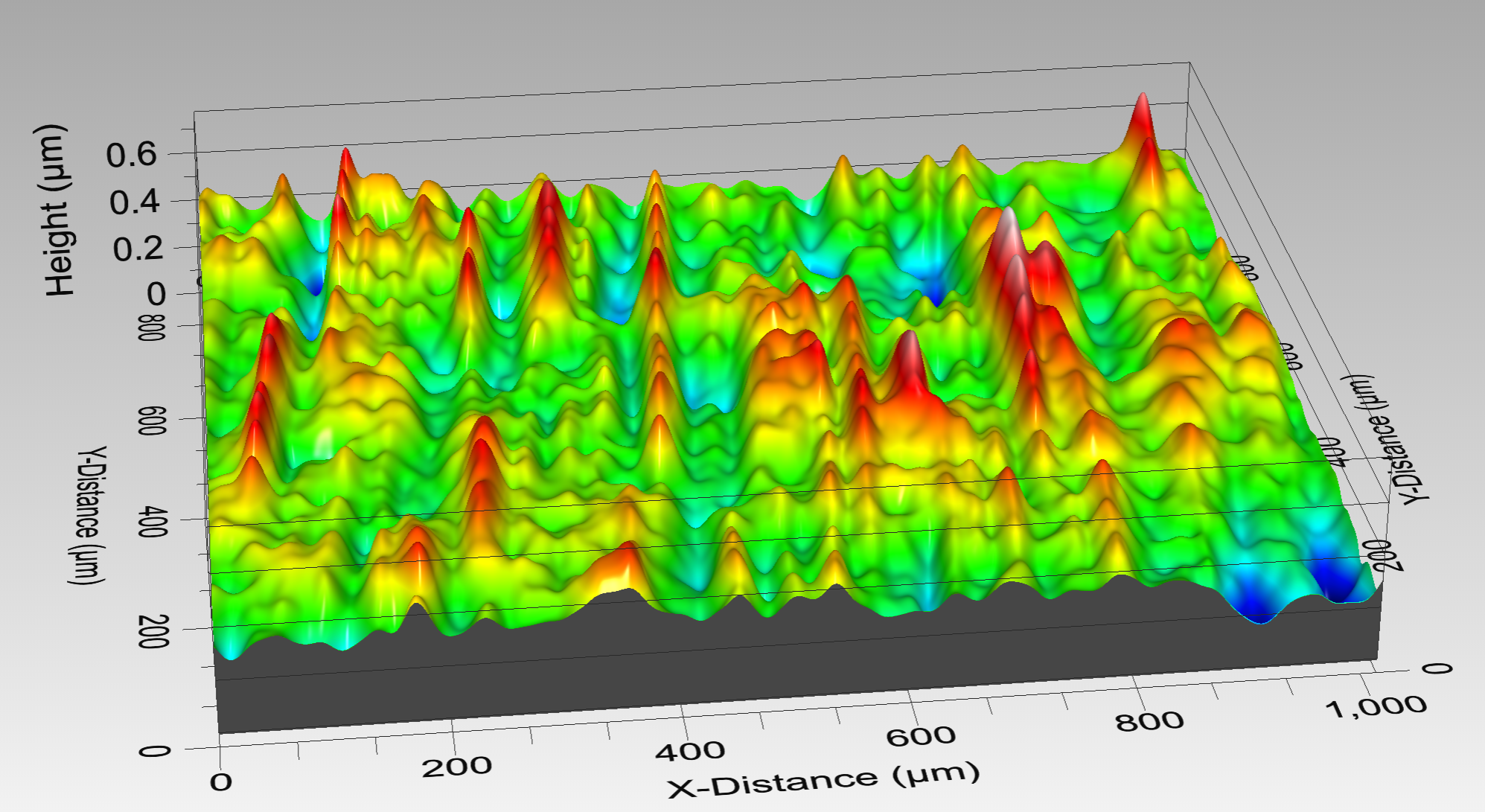
40 µm Low Pass Filter - Removed Frequencies Image |
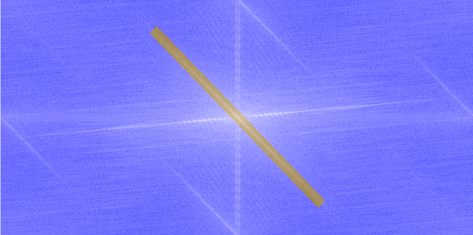
Manual filtering allows selection of the exact Fourier components to be attenuated by the FFT filter. Feature selection works similarly to the Flatten operator, where regions are selected using rectangular or circular contours, or a user-defined polygon. Remove Selected Frequencies excludes the selected region, which is shown in sepia tone. Keep Selected Frequencies adds a defined region inside an excluded zone. Note, as the PSD image is mirrored around the x and y access the software places a matching region in the conjugate spatial frequencies whenever an exclusion/inclusion region is defined.
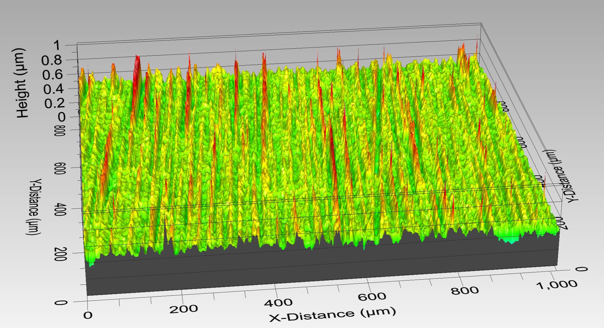
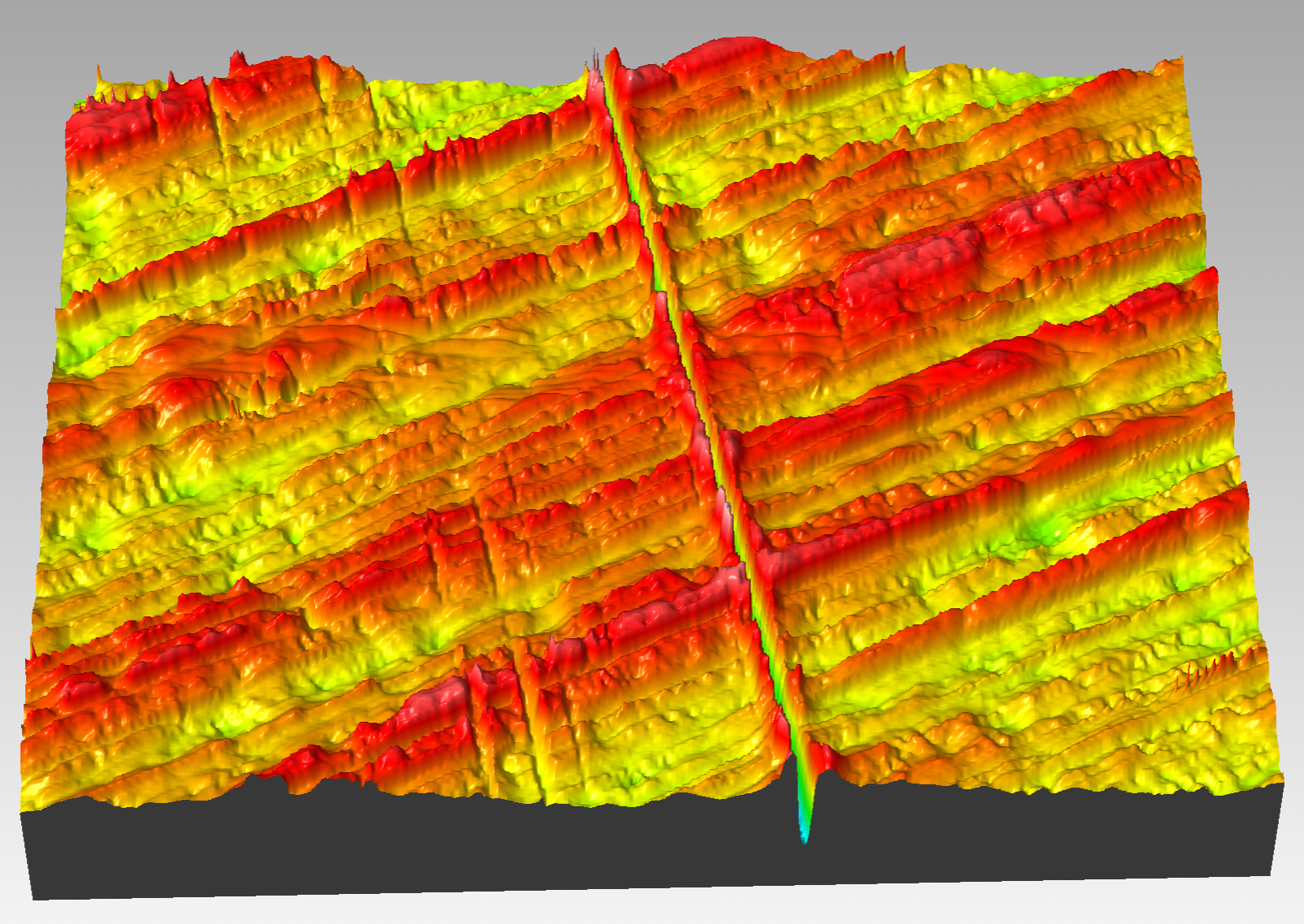
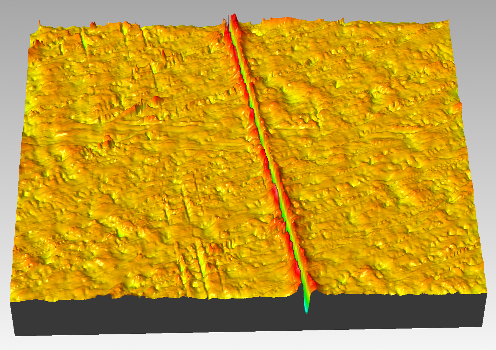
In the example below, the image contains a surface with a prevailing grain and a deep scratch. Using the Manual filter option, it was possible to remove the grain information from the image while leaving the feature of interest - the scratch - for further analysis.
 |
 |
 |
Original Image |
Power Spectrum Image with Excluded Region |
Output Included Image |