Measuring step height along a line in the sample is a three-step process:
1. Identify where on the sample to measure. 2. Select leveling points. 3. Identify the step location. |
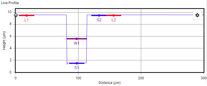 |
Example linear plot with level points (L1,L2), step height locations (S1,S2), and a trench feature (W1). |
To enable step height measurements, click the Step Height button under the Analysis section of the ribbon. The software will open a side panel showing the controls for the tool.
Select where to measure on the sample by clicking on the Top View image. The currently selected location is indicated by a red line across the sample. By default, this line starts at the center of the Top View image and measures horizontally across the sample. One end is highlighted by a green point, the other red. Move the measurement line by clicking on different locations in the Top View, or by clicking and dragging the red bar.
Click on either of the end points to switch to diagonal mode, which is explained a further down. To move the measurement location, click on the Top View image and the linear plot for that location is shown in the graph window below.
Change the direction to vertical using the Line Profile Orientation dialog. Choose the diagonal option to set a self-defined path. By moving around the Start and End points, the step height measurements are aligned to match desired features. The graph updates to scale appropriately based upon the length of the line.
Level the data using the level points built into the Step Height function by clicking the Go To Step 2 button. If the data has already been leveled using the Level or Form Removal functions, click Skip Leveling.
Level points are set by placing them on the Line Profile, displayed in the lower left corner of the screen. There are two points, labeled L1 and L2, indicated by vertical red lines surrounded by pink rectangles. The red line indicates the location of the leveling point, while the rectangles show the area around the leveling point used to determine the average height.
The width of these rectangles is determined by entering a value in the side panel underneath Width of the L1,L2 regions. Note, a wider range is more useful on rougher surfaces. Level points are moved by clicking and dragging either red line. Place the level points that both lie on the same plane of the surface with as much space as possible between them. Once suitable locations are selected, click Apply Leveling to continue.
Finally, set the step height locations. This function works similarly to the level function, but instead of placing both points on the same plane of the sample, one point is placed at the bottom of the step and one at the top. Determine the width of the step height regions by changing the Sampling Size value in the side panel. Other options are also available:
Measure Feature Width searches for certain types of features (lines and trenches) and determines their width. If there is more than one feature in the area of interest, you can also display the average feature width.
Materials enables the dissimilar materials function, which can be used to account for errors in step height measurement due to phase shifts in the reflection from different materials. For example, you may have a glass substrate coated with aluminum. Due to the phase shift caused by the differing reflectance properties of the surfaces, the software may incorrectly locate the top of the step relative to the substrate. Enabling Dissimilar Materials allows ProfilmOnline to correct for this problem in order to calculate an accurate step height.
When using this feature make sure to match the step height point with the material. In the example above, S1 should be aluminum for the top of the step, and S2 should be dielectric for glass.
Once both points are in the desired locations click Finish to show the results for step height, and trench width if enabled.